MVLEM - Multiple-Vertical-Line-Element-Model for RC Walls
- Command_Manual
- Tcl Commands
- Modeling_Commands
- model
- uniaxialMaterial
- ndMaterial
- frictionModel
- section
- geometricTransf
- element
- node
- sp commands
- mp commands
- timeSeries
- pattern
- mass
- block commands
- region
- rayleigh
- Analysis Commands
- Output Commands
- Misc Commands
- DataBase Commands
Developed and Implemented by:
Kristijan Kolozvari, California State University, Fullerton
Kutay Orakcal, Bogazici University, Istanbul, Turkey
John Wallace, Univeristy of California, Los Angeles
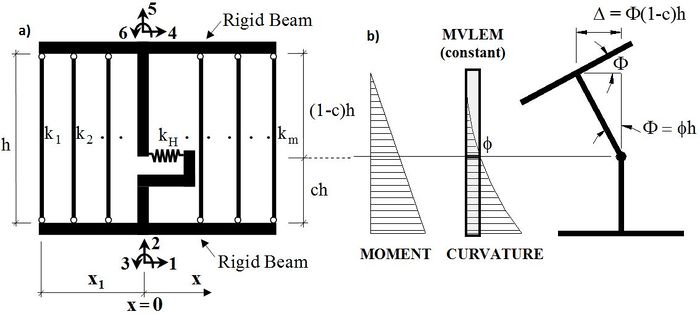
The MVLEM element command is used to generate a two-dimensional Multiple-Vertical-Line-Element-Model (MVLEM; Vulcano et al., 1988; Orakcal et al., 2004, Kolozvari et al., 2015) for simulation of flexure-dominated RC wall behavior. A single model element incorporates six global degrees of freedom, three of each located at the center of rigid top and bottom beams, as illustrated in Figure 1a. The axial/flexural response of the MVLEM is simulated by a series of uniaxial elements (or macro-fibers) connected to the rigid beams at the top and bottom (e.g., floor) levels, whereas the shear response is described by a shear spring located at height ch from the bottom of the wall element (Figure 1a). Shear and flexural responses of the model element are uncoupled. The relative rotation between top and bottom faces of the wall element occurs about the point located on the central axis of the element at height ch (Figure 1b). Rotations and resulting transverse displacements are calculated based on the wall curvature, derived from section and material properties, corresponding to the bending moment at height ch of each element (Figure 1b). A value of c=0.4 was recommended by Vulcano et al. (1988) based on comparison of the model response with experimental results.
Source: /usr/local/cvs/OpenSees/SRC/element/MVLEM/
Input Format:
| Element MVLEM $eleTag $Dens $iNode $jNode $m $c -thick {Thicknesses} -width {Widths} -rho {Reinforcing_ratios} -matConcrete {Concrete_tags} -matSteel {Steel_tags} -matShear {Shear_tag} |
| $eleTag | Unique element object tag |
| $Dens | Wall density |
| $iNode $jNode | End node tags |
| $m | Number of element macro-fibers |
| $c | Location of center of rotation from the iNode, c = 0.4 (recommended) |
| {Thicknesses} | Array of m macro-fiber thicknesses |
| {Widths} | Array of m macro-fiber widths |
| {Reinforcing_ratios} | Array of m reinforcing ratios corresponding to macro-fibers; for each fiber: rhoi = As,i/Agross,i (1 < i < m) |
| {Concrete _tags} | Array of m uniaxialMaterial tags for concrete |
| {Steel_tags} | Array of m uniaxialMaterial tags for steel |
| {Shear_tag} | Tag of uniaxialMaterial for shear material |
Element Recorders:
The following recorders are available with the MVLEM element:
| globalForce | Element global forces |
| Curvature | Element curvature |
| Shear_Force_Deformation | Element shear force-deformation relationship |
| Fiber_Strain | Vertical strains in m fibers along the cross-section |
| Fiber_Stress_Concrete | Vertical concrete stresses in m fibers along the cross-section |
| Fiber_Stress_Steel | Vertical steel stresses in m fibers along the cross-section |
Examples:
Element MVLEM 1 0.0 1 2 8 0.4 -thick 4 4 4 4 4 4 4 4 -width 7.5 1.5 7.5 7.5 7.5 7.5 1.5 7.5 -rho 0.0293 0.0 0.0033 0.0033
0.0033 0.0033 0.0 0.0293 -matConcrete 3 4 4 4 4 4 4 3 -matSteel 1 2 2 2 2 2 2 1 -matShear 5
Recorder Element -file MVLEM_Fgl.out -time -ele 1 globalForce
Recorder Element -file MVLEM_FiberStrain.out -time -ele 1 Fiber_Strain
References:
1) Kolozvari K., Orakcal K., and Wallace J. W. (2015). "Shear-Flexure Interaction Modeling of reinforced Concrete Structural Walls and Columns under Reversed Cyclic Loading", Pacific Earthquake Engineering Research Center, University of California, Berkeley, PEER Report No. 2015/12
2) Orakcal K. (2004). "Nonlinear Modeling and Analysis of Slender Reinforced Concrete Walls", PhD Dissertation, Department of Civil and Environmental Engineering, University of California, Los Angeles.
3) Orakcal K., Conte J.P., and Wallace J.W. (2004). “Flexural Modeling of Reinforced Concrete Structural Walls - Model Attributes”, ACI Structural Journal, V. 101, No. 5, pp 688-698.
4) Orakcal K. and Wallace J.W. (2006). “Flexural Modeling of Reinforced Concrete Structural Walls – Experimental Verification”, ACI Structural Journal, V. 103, No. 2, pp. 196-206.
5) Vulcano A., Bertero V.V., and Colotti V. (1988). “Analytical Modeling of RC Structural Walls”, Proceedings, 9th World Conference on Earthquake Engineering, V. 6, Tokyo-Kyoto, Japan, pp. 41-46.
Example 1. Simulation of Flexural Behavior of a Slender RC Wall Specimen under Cyclic Loading using MVLEM Model
Application of the MVLEM element for simulation of flexural response of RC walls is illustrated using the RC wall specimen RW2 tested by Thomsen and Wallace (1995). The specimen was tested under constant axial load and cyclic lateral displacement history applied at the top of the wall. Input parameters and selected output results are presented in the following sections.
E1.1. Model Calibration
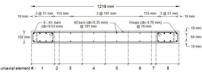
Specimen RW2 was 144 in tall, 48 in wide and 4 in thick, resulting in aspect ratio of 3.0 (slender wall). Figure E1.1 displays model discretization of the RW2 cross-section, with eight uniaxial elements defined along the length of the wall. The analytical model was discretized along wall height with 16 MVLEM elements with element heights in agreement with instrumentation provided on the specimen to allow consistent strain comparisons between model and experimental results. The material models were calibrated to match as tested material properties. Details about model calibration and experimental validation are provided by Orakcal (2004), and Orakcal and Wallace (2004).
E1.2. Input Files
Input files (.tcl) used to build the wall model and perform displacement-controlled analysis can be found in Example 1. MVLEM.zip:
- MVLEM_RW2.tcl – model generation and definition of analysis parameters
- gravity.tcl – application of gravity load
- dispControl.tcl – application of lateral displacement history (run this file)
- LibAnalysisStaticParameters.tcl - definition of static analysis parameters
- LibGeneratePeaks.tcl - generation of displacement history
E1.3. Analysis Results
Flexural load-deformation responses predicted by the MVLEM model and measured during the experiment are shown on Figure E1.2.
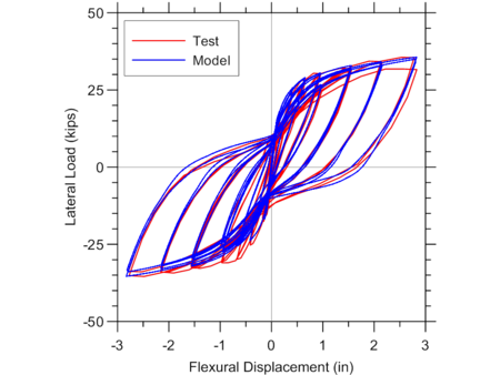
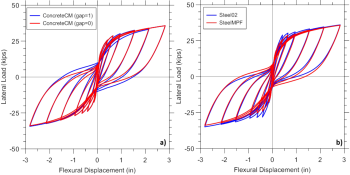
Figure E1.3 illustrates the sensitivity of analytical predictions obtained using the MVLEM to the optional gap closure parameter of the ConcreteCM model (-GapClose $gap), which allows consideration of different intensities of gradual gap closure in concrete (Figure E1.3a), as well as selection of the steel material model SteelMPF versus Steel02 (Figure E1.3b). It can be observed from Figure E1.3a that pinching characteristics of the response are slightly more pronounced when less gradual gap closure versus more gradual gap closure (i.e., gap=0 versus gap=1) is adopted. Figure E1.3b illustrates that the wall yield capacity as well as pinching characteristics of the behavior predicted by the MVLEM vary slightly when SteelMPF versus Steel02 is used.
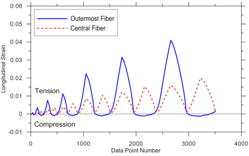
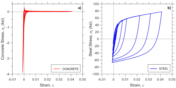
For illustration purposes, additional response predictions obtained using the MVLEM model are presented in Figure E1.4 and Figure E1.5, where analytically-predicted strain histories at the outermost and central wall fibers, and concrete and steel strain-stress relationships at the outermost fiber are presented, respectively. Responses are obtained using MVLEM recorders Fiber_Strain, Fiber_Stress_Concrete, and Fiber_Stress_Steel.
