Earthquake in Any Direction
Apply Earthquake in Any Direction
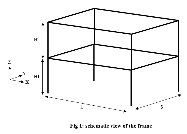
In this example we want to apply earthquake in any direction to a 3D elastic frame by using UniformExcitation command in OpenSEES software. Presented method is usable for any other 3D structure. In OpenSEES by UniformExcitation command we can apply acceleration in global directions. But it is not possible to apply acceleration in a direction other than global directions. To gain this end we have to rotate model through an introduced angle. So model geometry is dependent on that angle. The intended frame is a one bay two story elastic frame as in fig 1.
In this frame we tried to introduce parameters for all of geometric components. Parameters L and S are used for bay length in parallel with global X and Y directions, respectively (not rotated frame). H1 and H2 are story heights.
Model Dimension:
As it is a 3D frame model it has 3 dimension with 6 degrees of freedom at each node. So the model basic command is as follow: wipe ; model BasicBuilder -ndm 3 -ndf 6 ; Define Parameters: Parameters of this model are as follow:
- Define Parameters
set L 7.0 ; set S 4.0 ; set H1 3.0 ; set H2 3.0 ;
set Alpha 30.0 ; set Pi 3.14 ; set g 9.81 ;
- Loads (Kg/m2)
set DL 500.0 set LL 200.0 set ang [expr int($Alpha)] ; set FileName "OutPut_$ang" ; file mkdir $FileName ;
Parameters L, S, H1 and H2 are geometric parameters and defined with set command. Note that units that are used in this model are N, m and sec. Alpha is the angle between longitudinal direction of the frame and global X direction in degrees. DL and LL are distributed dead and live load of the floors in kg/m2. In last two lines we create a folder that contain the rotation angle in its name.
Define Nodes:
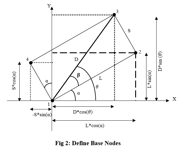
This step is one of the important steps in this model procedure as their coordinates have to define dependent to rotation angle. In fig 2 you can see location of base nodes as function of rotation angle. Other nodes of first and second floor are defined such base nodes with deferent Z coordinates. Global X and Y directions are shown un fig 2. We define nodes 1 to 4 as function of rotation angle, considering node 1 to be origin of the global coordinates. We define new parameter D to be diameter of the rectangular shape plan, also beta and theta are new angels that are shown in fig 2.
As angels have to define in radian we create new parameter, AlphaRad, to make degrees to radian for next calculations. All nodes of the frame are defined as follow:
Boundary Conditions:
In this frame all base nodes are fix to represent fix support as follow:
Define Elements:
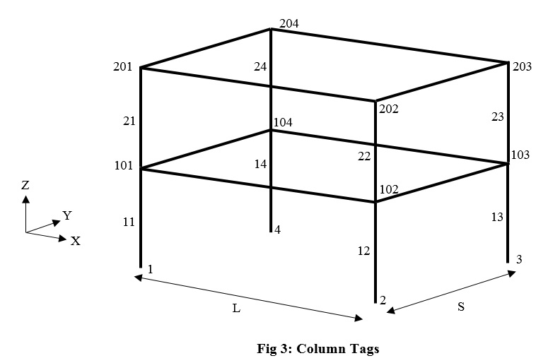
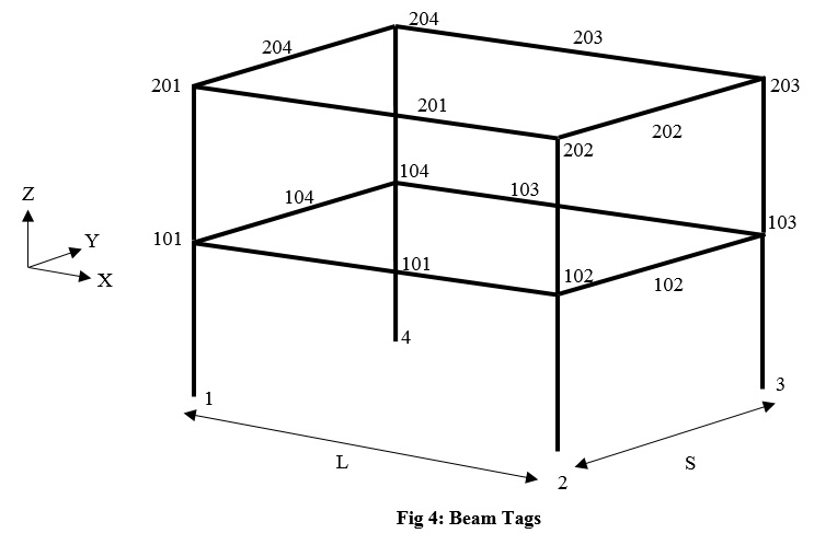
In this step we define elastic elements of the frame. The manner of numbering elements is shown in fig 3 and fig 4:


