ZeroLengthImpact3D
- Command_Manual
- Tcl Commands
- Modeling_Commands
- model
- uniaxialMaterial
- ndMaterial
- frictionModel
- section
- geometricTransf
- element
- node
- sp commands
- mp commands
- timeSeries
- pattern
- mass
- block commands
- region
- rayleigh
- Analysis Commands
- Output Commands
- Misc Commands
- DataBase Commands
This command constructs a node-to-node zero-length contact element in 3D space.
| element zeroLengthImpact3D $tag $slaveNode $masterNode $direction $initGap $frictionRatio $Kt $Kn $Kn2 $Delta_y $cohesion |
| $eleTag | unique element object tag |
| $sNode | Slave Node tag |
| $mNode | Master node tag |
| $Nodes ... | Slave and master node tags respectively |
| $Kn | Penalty in normal direction |
| $Kt | Penalty in tangential direction |
| $mu | friction coefficient |
| $c | cohesion (not available in 2D) |
| $dir | Direction flag of the contact plane (3D), it can be:
1 Out normal of the master plane pointing to +X direction 2 Out normal of the master plane pointing to +Y direction 3 Out normal of the master plane pointing to +Z direction |
NOTES:
- The contact element is node-to-node contact. Contact occurs between two contact nodes when they come close. The relation follows Mohr-coulomb law: T = $mu * N + $c, where T is tangential force and N is normal force across the interface. $mu is friction coefficient and $c is total cohesion (summed over the effective area of contact nodes)
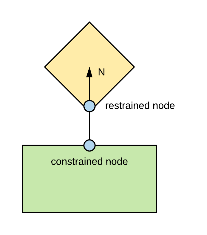
- The contact node pair in node-to-node contact element is termed "master node" and "slave node", respectively. Master/slave plane is the contact plane which the master/slave node belongs to. The discrimination is made solely for contact detection purpose. User need to specify the corresponding out normal of the master plane, and this direction is assumed to be unchanged during analysis. For simplicity, 3D contact only allows 3 options to specify the directions of the contact plane. The convention is: out normal of master plane always points to positive axial direction (+X or +Y, or +Z)
- For 2D contact, slave nodes and master nodes must be 2 DOF. For 3D contact, slave nodes and master nodes must be 3 DOF.
- The resulted tangent from the contact element is NON-SYMMETRIC. Switch to non-symmetric matrix solver.
EXAMPLES:
Gang Wang to provide a smart example!
REFERENCES:
Code Developed by: Arash E. Zaghi, Majid Cashany, University of Connecticut (UConn)
