User talk:Kkolozvari
Element MVLEM
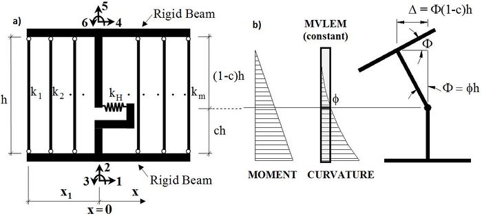
The MVLEM element command is used to generate a two-dimensional Multiple-Vertical-Line-Element-Model (MVLEM; Vulcano et al., 1988; Orakcal et al., 2004) for simulation of flexure-dominated RC wall behavior. A single model element incorporates six global degrees of freedom, three of each located at the center of rigid top and bottom beams, as illustrated in Figure 1a. The axial/flexural response of the MVLEM is simulated by a series of uniaxial elements (or macro-fibers) connected to the rigid beams at the top and bottom (e.g., floor) levels, whereas the shear response is described by a shear spring located at height ch from the bottom of the wall element. Shear and flexural responses of the model element are uncoupled. The relative rotation between top and bottom faces of the wall element occurs about the point located on the central axis of the element at height ch (Figure 1b). Rotations and resulting transverse displacements are calculated based on the wall curvature, derived from section and material properties, corresponding to the bending moment at height ch of each element (Figure 1b). A value of c=0.4 was recommended by Vulcano et al. (1988) based on comparison of the model response with experimental results.
Source: /usr/local/cvs/OpenSees/SRC/element/MVLEM/

Input Format:
| Element MVLEM $eleTag $Dens $iNode $jNode $m $c -thick <Thicknesses> -width <Widths> -rho <Reinforcing_ratios> -matConcrete <Concrete_tags> -matSteel <Steel_tags> -matShear <Shear_tag> |
| $eleTag | Unique element object tag |
| $Dens | Wall density |
| $iNode $jNode | End node tags |
| $m | Number of element macro-fibers |
| $c | Location of center of rotation with from the iNode, c = 0.4 (recommended) |
| <Thicknesses> | Array of m macro-fiber thicknesses |
| <Widths> | Array of m macro-fiber widths |
| <Reinforcing_ratios> | Array of m reinforcing ratios corresponding to macro-fibers; for each fiber: rho,i = As,i/Agross,i (1 < i < m) |
| <Concrete _tags> | Array of m uniaxialMaterial tags for concrete |
| <Steel_tags> | Array of m uniaxialMaterial tags for steel |
| <Shear_tag> | Tag of uniaxialMaterial for shear material |
Element Recorders:
The following recorders are available with the MVLEM element:
| globalForce | Element global forces |
| Curvature | Element curvature |
| Shear_Force_Deformation | Element shear force-deformation relationship |
| Fiber_Strain | Vertical strain in m fibers along the cross-section |
| Fiber_Stress_Concrete | Vertical concrete stress in m fibers along the cross-section |
| Fiber_Stress_Steel | Vertical steel stress in m fibers along the cross-section |
Examples:
Element MVLEM 1 0.0 1 2 8 0.4 -thick 4 4 4 4 4 4 4 4 -width 7.5 1.5 7.5 7.5 7.5 7.5 1.5 7.5 -rho 0.0293 0.0 0.0033 0.0033
0.0033 0.0033 0.0 0.0293 -matConcrete 3 4 4 4 4 4 4 3 -matSteel 1 2 2 2 2 2 2 1 -matShear 5
Recorder Element -file MVLEM_Fgl.out -time -ele 1 globalForce
Recorder Element -file MVLEM_FiberStrain.out -time -ele 1 Fiber_Strain
References:
Developed and Implemented by:
Kristijan Kolozvari, California State University Fullerton
Kutay Orakcal, Bogazici University, Istanbul
John Wallace, Univeristy of California, Los Angeles
1) Vulcano A., Bertero V.V., and Colotti V. (1988). “Analytical Modeling of RC Structural Walls”, Proceedings, 9th World Conference on Earthquake Engineering, V. 6, Tokyo-Kyoto, Japan, pp. 41-46.
2) Orakcal K., Conte J.P., and Wallace J.W. (2004). “Flexural Modeling of Reinforced Concrete Structural Walls - Model Attributes”, ACI Structural Journal, V. 101, No. 5, pp 688-698.
Element SFI_MVLEM
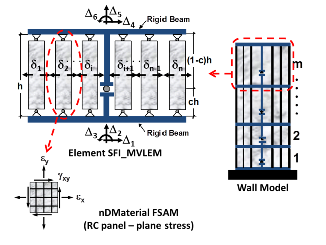
The SFI_MVLEM command is used to construct a Shear-Flexure Interaction Multiple-Vertical-Line-Element Model (SFI-MVLEM, Kolozvari et al., 2014a, b), which captures interaction between axial/flexural and shear behavior of RC structural walls and columns under cyclic loading. The SFI_MVLEM element (Figure 1) incorporates 2-D RC panel behavior described by the Fixed-Strut-Angle-Model (nDMaterial FSAM; Ulugtekin, 2010; Orakcal et al., 2012), into a 2-D macroscopic fiber-based model (MVLEM). The interaction between axial and shear behavior is captured at each RC panel (macro-fiber) level, which further incorporates interaction between shear and flexural behavior at the SFI_MVLEM element level.
Source: /usr/local/cvs/OpenSees/SRC/element/SFI_MVLEM/

Input Format:
| Element SFI_MVLEM $eleTag $iNode $jNode $m $c -thick <Thicknesses> -width <Widths> -mat <Material_tags> |
| $eleTag | Unique element object tag |
| $iNode $jNode | End node tags |
| $m | Number of element macro-fibers |
| $c | Location of center of rotation with from the iNode, c = 0.4 (recommended) |
| <Thicknesses> | Array of m macro-fiber thicknesses |
| <Widths> | Array of m macro-fiber widths |
| <Material_tags> | Array of m macro-fiber nDMaterial tags |
Element Recorders:
The following recorders are available with the SFI_MVLEM element:
| globalForce | Element global forces |
| Curvature | Element curvature |
| ShearDef | Element shear deformation |
| RCPanel $fibTag $Response | Returns RC panel (macro-fiber) $Response for a $fibTag-th panel (1 ≤ fibTag ≤ m). For available $Response-s refer to nDMaterial FSAM (LINK). |
Examples:
Element SFI_MVLEM 1 1 2 5 0.4 -thick 6 6 6 6 6 -width 9 10 10 10 9 -mat 7 6 6 6 7
Recorder Element -file SFI_MVLEM_Fgl.out -time -ele 1 2 3 globalForce
Recorder Element -file SFI_MVLEM_panel_strain.out -time -ele 1 RCPanel 1 panel_strain
References:
Developed and Implemented by:
Kristijan Kolozvari, California State University Fullerton
Kutay Orakcal, Bogazici University, Istanbul
John Wallace, Univeristy of California, Los Angeles
1) Kolozvari K., Orakcal K., and Wallace J. W. (2015). ”Modeling of Cyclic Shear-Flexure Interaction in Reinforced Concrete Structural Walls. I: Theory”, ASCE Journal of Structural Engineering, 141(5), 04014135 doi
2) Kolozvari K., Tran T., Orakcal K., and Wallace, J.W. (2015). ”Modeling of Cyclic Shear-Flexure Interaction in Reinforced Concrete Structural Walls. II: Experimental Validation”, ASCE Journal of Structural Engineering, 141(5), 04014136 doi
3) Kolozvari K. (2013). “Analytical Modeling of Cyclic Shear-Flexure Interaction in Reinforced Concrete Structural Walls”, PhD Dissertation, University of California, Los Angeles.
uniaxialMaterial SteelMPF
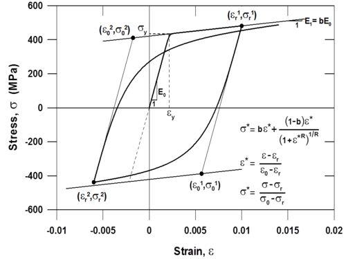
This command is used to construct a uniaxialMaterial SteelMPF, which represents the well-known uniaxial constitutive nonlinear hysteretic material model for steel proposed by Menegotto and Pinto (1973), and extended by Filippou et al. (1983) to include isotropic strain hardening effects. The relationship is in the form of curved transitions (Figure 1), each from a straight-line asymptote with slope E0 (modulus of elasticity) to another straight-line asymptote with slope E1 = bE0 (yield modulus) where b is the strain hardening ratio. The curvature of the transition curve between the two asymptotes is governed by a cyclic curvature parameter R, which permits the Bauschinger effect to be represented, and is dependent on the absolute strain difference between the current asymptote intersection point and the previous maximum or minimum strain reversal point depending on whether the current strain is increasing or decreasing, respectively. The strain and stress pairs (<math>\epsilon</math>r,<math>\sigma</math>r) and (<math>\epsilon</math>0,<math>\sigma</math>0) shown on Figure 1 are updated after each strain reversal.
Source: /usr/local/cvs/OpenSees/SRC/material/uniaxial/

Input Format:
| uniaxialMaterial SteelMPF $mattag $fyp $fyn $E0 $bp $bn $R0 $a1 $a2 <$a3 $a4> |
| $mattag | Unique nDMaterial tag |
| $fyp | Yield strength in tension (positive loading direction) |
| $$fyn | Yield strength in compression (negative loading direction) |
| $E0 | Initial tangent modulus |
| $bp | Strain hardening ratio in tension (positive loading direction) |
| $bn | Strain hardening ratio in compression ( negative loading direction) |
| $R0 | Initial value of the curvature parameter R (R0 = 20 recommended) |
| $a1 | Curvature degradation parameter (a1 = 18.5 recommended) |
| $a2 | Curvature degradation parameter (a2 = 0.15 or 0.0015 recommended) |
| $a3 | Isotropic hardening parameter (optional, default = 0.01) |
| $a4 | Isotropic hardening parameter (optional, default = 7.0) |
Example:
uniaxialMaterial SteelMPF 1 60 60 29000 0.02 0.02 20.0 18.5 0.15
Discussion:
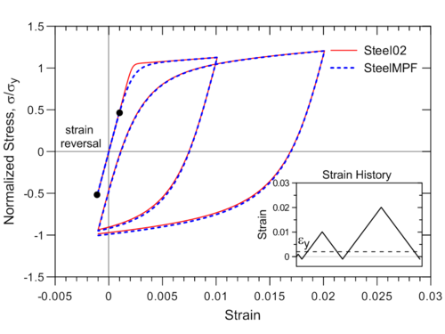
Although the Menegotto-Pinto model is already available in OpenSees (e.g., Steel02), the formulation of SteelMPF brings several distinctive features compared to existing models. For example, the model allows definition of different yield stress values and strain hardening ratios for tension and compression, and it considers degradation of cyclic curvature parameter R for strain reversals in both pre- and post- yielding regions, which could produce more accurate predictions of yield capacity for some RC wall specimens (see Example 1), whereas Steel02 considers the degradation in post-yielding region only. Strain-stress relationships obtained using SteelMPF and Steel02 are compared in Figure 2 for a strain history that includes strain reversals at strain values equal to one-half of the yield strain (e.i., <math>\epsilon</math>r = ±0.001 = <math>\epsilon</math>y/2). The model also allows calibration of isotropic hardening parameters through optional input variables a3 and a4, and uses default values of a3 = 0.01 and a4 = 7.0 as calibrated by Filippou et al. (1983) based on test results. To disregard isotropic strain hardening behavior in SteelMPF, parameter a3 needs to be assigned a zero value (a3 = 0.0).

References:
Developed and Implemented by:
Kristijan Kolozvari, California State University Fullerton
Kutay Orakcal, Bogazici University, Istanbul
John Wallace, Univeristy of California, Los Angeles
1) Menegotto, M., and Pinto, P.E. (1973). Method of analysis of cyclically loaded RC plane frames including changes in geometry and non-elastic behavior of elements under normal force and bending. Preliminary Report IABSE, vol 13.
2) Filippou F.C., Popov, E.P., and Bertero, V.V. (1983). "Effects of Bond Deterioration on Hysteretic Behavior of Reinforced Concrete Joints". Report EERC 83-19, Earthquake Engineering Research Center, University of California, Berkeley.
uniaxialMaterial ConcreteCM
This command is used to construct a uniaxialMaterial SteelMPF, which represents the well-known uniaxial constitutive nonlinear hysteretic material model for steel proposed by Menegotto and Pinto (1973), and extended by Filippou et al. (1983) to include isotropic strain hardening effects. The relationship is in the form of curved transitions (Figure 1), each from a straight-line asymptote with slope E0 (modulus of elasticity) to another straight-line asymptote with slope E1 = bE0 (yield modulus) where b is the strain hardening ratio. The curvature of the transition curve between the two asymptotes is governed by a cyclic curvature parameter R, which permits the Bauschinger effect to be represented, and is dependent on the absolute strain difference between the current asymptote intersection point and the previous maximum or minimum strain reversal point depending on whether the current strain is increasing or decreasing, respectively. The strain and stress pairs (<math>\epsilon</math>r,<math>\sigma</math>r) and (<math>\epsilon</math>0,<math>\sigma</math>0) shown on Figure 1 are updated after each strain reversal.
Source: /usr/local/cvs/OpenSees/SRC/material/uniaxial/

Input Format:
| uniaxialMaterial SteelMPF $mattag $fyp $fyn $E0 $bp $bn $R0 $a1 $a2 <$a3 $a4> |
| $mattag | Unique nDMaterial tag |
| $fyp | Yield strength in tension (positive loading direction) |
| $$fyn | Yield strength in compression (negative loading direction) |
| $E0 | Initial tangent modulus |
| $bp | Strain hardening ratio in tension (positive loading direction) |
| $bn | Strain hardening ratio in compression ( negative loading direction) |
| $R0 | Initial value of the curvature parameter R (R0 = 20 recommended) |
| $a1 | Curvature degradation parameter (a1 = 18.5 recommended) |
| $a2 | Curvature degradation parameter (a2 = 0.15 or 0.0015 recommended) |
| $a3 | Isotropic hardening parameter (optional, default = 0.01) |
| $a4 | Isotropic hardening parameter (optional, default = 7.0) |
Example:
uniaxialMaterial SteelMPF 1 60 60 29000 0.02 0.02 20.0 18.5 0.15
Discussion:
Although the Menegotto-Pinto model is already available in OpenSees (e.g., Steel02), the formulation of SteelMPF brings several distinctive features compared to existing models. For example, the model allows definition of different yield stress values and strain hardening ratios for tension and compression, and it considers degradation of cyclic curvature parameter R for strain reversals in both pre- and post- yielding regions, which could produce more accurate predictions of yield capacity for some RC wall specimens (see Example 1), whereas Steel02 considers the degradation in post-yielding region only. Strain-stress relationships obtained using SteelMPF and Steel02 are compared in Figure 2 for a strain history that includes strain reversals at strain values equal to one-half of the yield strain (e.i., <math>\epsilon</math>r = ±0.001 = <math>\epsilon</math>y/2). The model also allows calibration of isotropic hardening parameters through optional input variables a3 and a4, and uses default values of a3 = 0.01 and a4 = 7.0 as calibrated by Filippou et al. (1983) based on test results. To disregard isotropic strain hardening behavior in SteelMPF, parameter a3 needs to be assigned a zero value (a3 = 0.0).

References:
Developed and Implemented by:
Kristijan Kolozvari, California State University Fullerton
Kutay Orakcal, Bogazici University, Istanbul
John Wallace, Univeristy of California, Los Angeles
1) Menegotto, M., and Pinto, P.E. (1973). Method of analysis of cyclically loaded RC plane frames including changes in geometry and non-elastic behavior of elements under normal force and bending. Preliminary Report IABSE, vol 13.
2) Filippou F.C., Popov, E.P., and Bertero, V.V. (1983). "Effects of Bond Deterioration on Hysteretic Behavior of Reinforced Concrete Joints". Report EERC 83-19, Earthquake Engineering Research Center, University of California, Berkeley.