DDM-Based Response Sensitivity Computation Tcl Commands:: Difference between revisions
Jump to navigation
Jump to search
Foxchameleon (talk | contribs) No edit summary |
Foxchameleon (talk | contribs) No edit summary |
||
| Line 1: | Line 1: | ||
<!-- INTRODUCTION --> | |||
<h1>Introduction</h1> | |||
The examples in this manual are listed in order of simplicity. | |||
NOTE: gravity analysis is always included as part of the model building | |||
<!-- MODELS --> | |||
<h1>Models</h1> | |||
The following types of models are represented in these examples: | |||
:;<h2>Elastic Elements</h2> | |||
: OpenSees [[Elastic Beam Column Element]] | |||
: The elastic, uncoupled, axial and flexural stiffnesses are defined at the element level | |||
: user specifies: E,I,A | |||
:;<h2>Inelastic Elements</h2> | |||
: OpenSees [[Force-Based Beam-Column Element]] | |||
: Two types of sections | |||
::<h3>Uniaxial Section</h3> | |||
::: The inelastic, uncoupled, axial and flexural stiffnesses are defined at the section level | |||
::: The OpenSees [[Uniaxial Section]] Command is used | |||
::: User specifies: | |||
:::: Axial stiffness A | |||
:::: Section Moment-Curvature characteristics via the OpenSees [[UniaxialMaterial Command]] | |||
::<h3>Fiber Section</h3> | |||
::: The section is broken down into fibers where uniaxial materials are defined independently. | |||
::: The program calculates the coupled flexural and axial stiffnesses/strength by integrating strains across the section | |||
::: The OpenSees [[Fiber Section]] Command is used | |||
::: User specifies | |||
:::: Stress-Strain characteristics via the OpenSees [[UniaxialMaterial Command]] for all number of materials | |||
:::: Section geometry via series of Patches and Layers in the fiber section | |||
::: Two Section Geometries are presented | |||
:::: *RC Rectangular Section | |||
:::: *Standard AISC W section | |||
<!-- LATERAL LOADS --> | |||
<h1>Lateral Loads</h1> | |||
The following types of lateral loads are represented in these examples: | |||
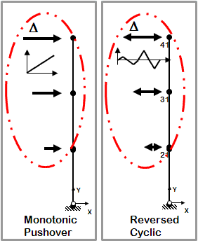
[[File:StaticPushoverLoads_Figure1.GIF|link=OpenSees Examples Manual -- Structural Models & Analyses|right]] | |||
:;<h2> Static Pushover</h2> | |||
: Control node is located at the highest floor | |||
: Lateral-load distribution is proportional the the mass distribution along the height of the building | |||
: Static analysis | |||
: Two types | |||
::<h3>Monotonic Pushover</h3> | |||
::: One-directional displacement-controlled static lateral loading | |||
::<h3>Reversed Cyclic Pushover</h3> | |||
::: One-directional displacement-controlled static lateral loading | |||
::: Displacement cycles are imposed in positive and negative direction | |||
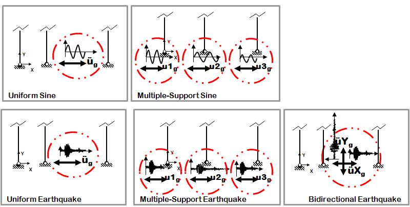
[[File:TimeDependent_Figure1.GIF|link=OpenSees Examples Manual -- Structural Models & Analyses|right]] | |||
:;<h2> Time-Dependent Dynamic Loads</h2> | |||
: Transient analysis | |||
: Four types | |||
::<h3>Uniform Sine-Wave</h3> | |||
::: Sine-wave acceleration input | |||
::: Same acceleration input at all nodes restrained in specified direction | |||
::<h3>Multiple-Support Sine-Wave</h3> | |||
::: Sine-wave displacement input | |||
::: Different displacements are specified at particular nodes in specified directions | |||
::<h3>Uniform Earthquake</h3> | |||
::: Earthquake (from file) acceleration input | |||
::: Same acceleration input at all nodes restrained in specified direction | |||
::<h3>Multiple-Support Earthquake</h3> | |||
::: Earthquake (from file) displacement input | |||
::: Different displacements are specified at particular nodes in specified direction | |||
::<h3>Bidirectional Earthquake</h3> | |||
::: Different inputs are specified for two directions | |||
::: Same acceleration input at all nodes restrained in specified direction | |||
The following Analysis commands are added to the interpreter to create the Analysis and perform the analysis: | The following Analysis commands are added to the interpreter to create the Analysis and perform the analysis: | ||
Revision as of 21:20, 9 January 2011
Introduction
The examples in this manual are listed in order of simplicity.
NOTE: gravity analysis is always included as part of the model building
Models
The following types of models are represented in these examples:
Elastic Elements
- OpenSees Elastic Beam Column Element
- The elastic, uncoupled, axial and flexural stiffnesses are defined at the element level
- user specifies: E,I,A
Inelastic Elements
- OpenSees Force-Based Beam-Column Element
- Two types of sections
Uniaxial Section
- The inelastic, uncoupled, axial and flexural stiffnesses are defined at the section level
- The OpenSees Uniaxial Section Command is used
- User specifies:
- Axial stiffness A
- Section Moment-Curvature characteristics via the OpenSees UniaxialMaterial Command
Fiber Section
- The section is broken down into fibers where uniaxial materials are defined independently.
- The program calculates the coupled flexural and axial stiffnesses/strength by integrating strains across the section
- The OpenSees Fiber Section Command is used
- User specifies
- Stress-Strain characteristics via the OpenSees UniaxialMaterial Command for all number of materials
- Section geometry via series of Patches and Layers in the fiber section
- Two Section Geometries are presented
- *RC Rectangular Section
- *Standard AISC W section
Lateral Loads
The following types of lateral loads are represented in these examples:

Static Pushover
- Control node is located at the highest floor
- Lateral-load distribution is proportional the the mass distribution along the height of the building
- Static analysis
- Two types
Monotonic Pushover
- One-directional displacement-controlled static lateral loading
Reversed Cyclic Pushover
- One-directional displacement-controlled static lateral loading
- Displacement cycles are imposed in positive and negative direction

Time-Dependent Dynamic Loads
- Transient analysis
- Four types
Uniform Sine-Wave
- Sine-wave acceleration input
- Same acceleration input at all nodes restrained in specified direction
Multiple-Support Sine-Wave
- Sine-wave displacement input
- Different displacements are specified at particular nodes in specified directions
Uniform Earthquake
- Earthquake (from file) acceleration input
- Same acceleration input at all nodes restrained in specified direction
Multiple-Support Earthquake
- Earthquake (from file) displacement input
- Different displacements are specified at particular nodes in specified direction
Bidirectional Earthquake
- Different inputs are specified for two directions
- Same acceleration input at all nodes restrained in specified direction
The following Analysis commands are added to the interpreter to create the Analysis and perform the analysis: