Corotational Transformation: Difference between revisions
(New page: This command is used to construct the Corotational Coordinate Transformation (CorotCrdTransf) object. Corotational transformation can be used in large displacement-small strain problems. N...) |
No edit summary |
||
| Line 1: | Line 1: | ||
{{CommandManualMenu}} | |||
This command is used to construct the Corotational Coordinate Transformation (CorotCrdTransf) object. Corotational transformation can be used in large displacement-small strain problems. NOTE: Currently the transformation does not deal with element loads and will ignore any that are applied to the element. | This command is used to construct the Corotational Coordinate Transformation (CorotCrdTransf) object. Corotational transformation can be used in large displacement-small strain problems. NOTE: Currently the transformation does not deal with element loads and will ignore any that are applied to the element. | ||
Revision as of 21:18, 3 March 2010
- Command_Manual
- Tcl Commands
- Modeling_Commands
- model
- uniaxialMaterial
- ndMaterial
- frictionModel
- section
- geometricTransf
- element
- node
- sp commands
- mp commands
- timeSeries
- pattern
- mass
- block commands
- region
- rayleigh
- Analysis Commands
- Output Commands
- Misc Commands
- DataBase Commands
This command is used to construct the Corotational Coordinate Transformation (CorotCrdTransf) object. Corotational transformation can be used in large displacement-small strain problems. NOTE: Currently the transformation does not deal with element loads and will ignore any that are applied to the element.
For a two-dimensional problem:
| geomTransf Corotational $transfTag <-jntOffset $dXi $dYi $dXj $dYj> |
For a three-dimensional problem:
| geomTransf Corotational $transfTag $vecxzX $vecxzY $vecxzZ <-jntOffset $dXi $dYi $dZi $dXj $dYj $dZj> |
| $transfTag | integer tag identifying transformation |
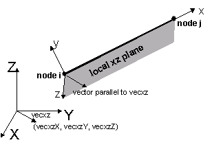
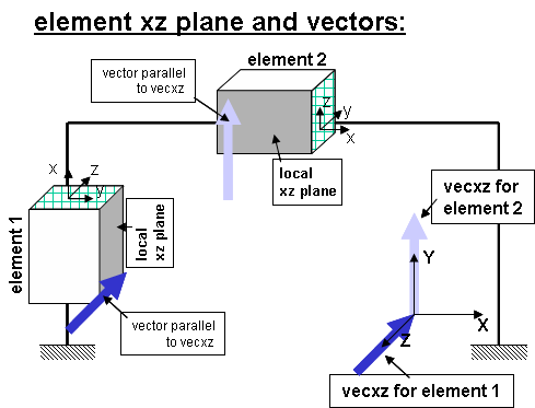
| $vecxzX $vecxzY $vecxzZ | X, Y, and Z components of vecxz, the vector used to define the local x-z plane of the local-coordinate system. The local y-axis is defined by taking the cross product of the vecxz vector and the x-axis.
These components are specified in the global-coordinate system X,Y,Z and define a vector that is in a plane parallel to the x-z plane of the local-coordinate system. These items need to be specified for the three-dimensional problem. |
| $dXi $dYi $dZi | joint offset values -- absolute offsets specified with respect to the global coordinate system for element-end node i (the number of arguments depends on the dimensions of the current model) (optional) |
| $dXj $dYj $dZj | joint offset values -- absolute offsets specified with respect to the global coordinate system for element-end node j (the number of arguments depends on the dimensions of the current model) (optional) |
The element coordinate system is specified as follows:
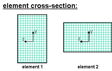
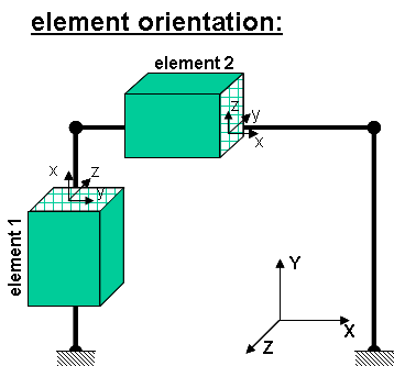
The x-axis is the axis connecting the two element nodes; the y- and z-axes are then defined using a vector that lies on a plane parallel to the local x-z plane -- vecxz. The local y-axis is defined by taking the cross product of the vecxz vector and the x-axis.. The section is attached to the element such that the y-z coordinate system used to specify the section corresponds to the y-z axes of the element.
EXAMPLE:
- Element 1 : tag 1 : vecxZ = zaxis
geomTransf Corotational 1 0 0 -1
- Element 2 : tag 2 : vecxZ = y axis
geomTransf Corotational 2 0 1 0
Code Developed by: Remo Magalhaes de Souza
Images Developed by: Silvia Mazzoni
