ZeroLengthInterface2D: Difference between revisions
mNo edit summary |
No edit summary |
||
| Line 39: | Line 39: | ||
'''EXAMPLE:''' | '''EXAMPLE:''' | ||
[[File: | [[File:ZeroLengthInterface2Drc.png]] | ||
element zeroLengthInterface2D 1 -sNdNum 6 -mNdNum 6 –dof 2 3 -Nodes 5 10 12 3 9 11 1 4 2 8 7 | element zeroLengthInterface2D 1 -sNdNum 6 -mNdNum 6 –dof 2 3 -Nodes 5 10 12 3 9 11 1 4 2 8 7 6 1e8 1e8 16 | ||
'''Example 1:''' | '''Example 1:''' | ||
Latest revision as of 15:58, 14 June 2020
- Command_Manual
- Tcl Commands
- Modeling_Commands
- model
- uniaxialMaterial
- ndMaterial
- frictionModel
- section
- geometricTransf
- element
- node
- sp commands
- mp commands
- timeSeries
- pattern
- mass
- block commands
- region
- rayleigh
- Analysis Commands
- Output Commands
- Misc Commands
- DataBase Commands
zeroLengthInterface2D is Node-to-Segment (NTS) frictional contact element used in two dimensional analysis for contact between elements. Please notice that any number of DOF (DOF>1) can be handled using this element (i.e. beam-solid, solid-solid as well as beam-beam contact) as oppose to zeroLengthContactNTS2D element).
| element zeroLengthInterface2D $eleTag -cNdNum $cNdNum -rNdNum $rNdNum –dof $cdof $rdof -Nodes $Nodes $Kn $Kt $phi |
| $eleTag | unique element object tag |
| $cNdNum | Number of Constrained Nodes |
| $rNdNum | Number of Retained nodes |
| $cdof $rdof | Constrained and Retained degree of freedom |
| $Nodes ... | Constrained and Retained node tags respectively |
| $Kn | Penalty in normal direction |
| $Kt | Penalty in tangential direction |
| $phi | Friction angle in degrees |
NOTES:
- The contact element is node-to-segment (NTS) contact. The relation follows Mohr-Coulomb frictional law: <math>T = N \times tan(\phi)</math>, where <math>T</math> is the tangential force, <math>N</math> is normal force across the interface and <math>\phi\,\!</math> is friction angle.
- For 2D contact, constrained nodes and retained nodes must be 2 DOF and notice that the constrained and retained nodes must be entered in counterclockwise order.
- The resulting tangent from the contact element is non-symmetric. Switch to the non-symmetric matrix solver if convergence problem is experienced.
- As opposed to node-to-node contact, predefined normal vector for node-to-segment (NTS) element is not required because contact normal will be calculated automatically at each step. And also this element can handle contact between different DOFs such as beam-beam, beam-solid and solid-solid.
- contact element is implemented to handle large deformations.
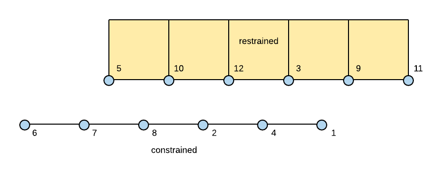
EXAMPLE:
element zeroLengthInterface2D 1 -sNdNum 6 -mNdNum 6 –dof 2 3 -Nodes 5 10 12 3 9 11 1 4 2 8 7 6 1e8 1e8 16
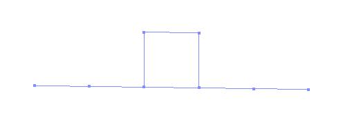
Example 1:
This example simply shows the quadrilateral elements in normal contact on top of beam element. The top element is in normal downward uniform force. The Tcl script of this example can be found here.
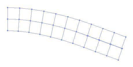
Example 2:
This example shows two cantilever beams in contact. The beams were modeled using four-node quadrilateral elements and the end of top beam was subjected to a linearly increasing displacement. The Tcl scripts for this example can be found here.
The following Figure shows the deflections of the two beams.
REFERENCES:
- P. Wriggers, V.T. Vu and E. Stein, Finite-element formulation of large deformation impact–contact problems with friction, Comput. Struct. 37 (1990), pp. 319–331.
- Peter Wriggers. Computational Contact Mechanics. John Wiley & Sons Ltd. Chichester, 2002.
Code Developed by: Roozbeh G. Mikola, UC Berkeley and N. Sitar, UC Berkeley


