ZeroLengthImpact3D: Difference between revisions
Jump to navigation
Jump to search
No edit summary |
No edit summary |
||
| Line 49: | Line 49: | ||
# For simulating master and slave contact surfaces, this element can be defined for pairs of nodes on master and slave surface. | # For simulating master and slave contact surfaces, this element can be defined for pairs of nodes on master and slave surface. | ||
<!-- | |||
---- | ---- | ||
SAMPLE COMMAND (example scripts are available at bottom of this page): | SAMPLE COMMAND (example scripts are available at bottom of this page): | ||
| Line 65: | Line 66: | ||
[[ Impact_Material | ImpactMaterial ]] | [[ Impact_Material | ImpactMaterial ]] | ||
---- | |||
---- | |||
---- | ---- | ||
Revision as of 20:57, 29 May 2013
- Command_Manual
- Tcl Commands
- Modeling_Commands
- model
- uniaxialMaterial
- ndMaterial
- frictionModel
- section
- geometricTransf
- element
- node
- sp commands
- mp commands
- timeSeries
- pattern
- mass
- block commands
- region
- rayleigh
- Analysis Commands
- Output Commands
- Misc Commands
- DataBase Commands
This command constructs a node-to-node zero-length contact element in 3D space.
| element zeroLengthImpact3D $tag $slaveNode $masterNode $direction $initGap $frictionRatio $Kt $Kn $Kn2 $Delta_y $cohesion |
| $tag | Unique element object tag |
| $slaveNode | Slave node tag |
| $masterNode | Master node tag |
| $direction |
1 if normal vector of master plane points to +X direction 2 if normal vector of master plane points to +Y direction 3 if normal vector of master plane points to +Z direction |
| $initGap | Initial gap between master plane and slave plane |
| $frictionRatio | Friction ratio |
| $Kt | Penalty in tangential directions (parallel to master and slave planes) |
| $Kn | Penalty in normal direction (normal to master and slave planes) |
| $Kn2 | Penalty in normal direction after yielding based on Hertz impact model |
| $Delta_y | Yield deformation based on Hertz impact model |
| $cohesion | Cohesion, if no cohesion, it is zero |
NOTES:
- This element has been developed on top of the “zeroLengthContact3D”. All the notes available in “zeroLengthContact3D” wiki page would apply to this element as well. It includes the definition of master and slave nodes, the number of degrees of freedom in the domain, etc. Please refer to “zeroLengthContact3D” for detailed descriptions.
- This element adds the capabilities of “ImpactMaterial” to “zeroLengthContact3D”, without the need for extra nodes and elements in the modeling process. That is the capability of having an initial gap in the normal direction and also the capability of considering energy dissipation due to pounding/impact in the normal direction.
- This element has been employed to simulate the bridge hinge movements like superstructure-abutment interaction in bridges at University of Connecticut (UConn) and University of Nevada, Reno (UNR). This element was found to be fast-converging and eliminating the need for many extra elements and nodes in the modeling process.
- For simulating master and slave contact surfaces, this element can be defined for pairs of nodes on master and slave surface.
REFERENCES:
Code Developed by: Dr. A.E. Zaghi, M. Cashany @ University of Connecticut (UConn)
EXAMPLE SCRIPT: The following zip file contains an example script and the corresponding input cyclic displacement:
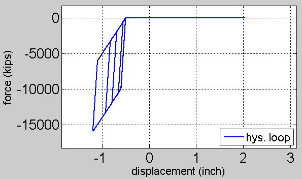
After running the example script, the following hysteresis loop is resulted in normal direction under cyclic excitation:
