Triple Friction Pendulum Bearing Element: Difference between revisions
No edit summary |
No edit summary |
||
| (10 intermediate revisions by 2 users not shown) | |||
| Line 3: | Line 3: | ||
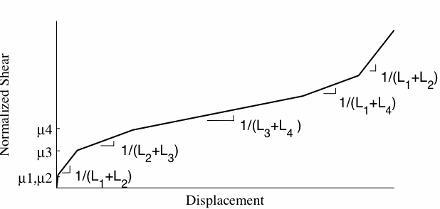
This command is used to construct a Triple Friction Pendulum Bearing element object, which is defined by two nodes. The element can have zero length or the appropriate bearing height. The bearing has unidirectional (2D) or coupled (3D) friction properties (with post-yield stiffening due to the concave sliding surface) for the shear deformations, and force-deformation behaviors defined by UniaxialMaterials in the remaining two (2D) or four (3D) directions. To capture the uplift behavior of the bearing, the user-specified UniaxialMaterial in the axial direction is modified for no-tension behavior. P-Delta moments are entirely transferred to the concave sliding surface (iNode). It is important to note that rotations of the concave sliding surface (rotations at the iNode) affect the shear behavior of the bearing. If the element has non-zero length, the local x-axis is determined from the nodal geometry unless the optional x-axis vector is specified in which case the nodal geometry is ignored and the user-defined orientation is utilized. | This command is used to construct a Triple Friction Pendulum Bearing element object, which is defined by two nodes. The element can have zero length or the appropriate bearing height. The bearing has unidirectional (2D) or coupled (3D) friction properties (with post-yield stiffening due to the concave sliding surface) for the shear deformations, and force-deformation behaviors defined by UniaxialMaterials in the remaining two (2D) or four (3D) directions. To capture the uplift behavior of the bearing, the user-specified UniaxialMaterial in the axial direction is modified for no-tension behavior. P-Delta moments are entirely transferred to the concave sliding surface (iNode). It is important to note that rotations of the concave sliding surface (rotations at the iNode) affect the shear behavior of the bearing. If the element has non-zero length, the local x-axis is determined from the nodal geometry unless the optional x-axis vector is specified in which case the nodal geometry is ignored and the user-defined orientation is utilized. | ||
[[Image: | [[Image:TFP_backbone.gif]] | ||
{| | {| | ||
| Line 64: | Line 64: | ||
|} | |} | ||
[[File:TFPwH0.gif]] | |||
[[File:TFP_displaced.gif]] | |||
NOTE: | NOTE: | ||
If the element has zero length and optional orientation vectors are not specified, the local element axes coincide with the global axes. Otherwise the local z-axis is defined by the cross product between the x- and y-vectors specified on the command line. | #If the element has zero length and optional orientation vectors are not specified, the local element axes coincide with the global axes. Otherwise the local z-axis is defined by the cross product between the x- and y-vectors specified on the command line. | ||
#The valid queries to a triple friction pendulum bearing element when creating an ElementRecorder object are 'force,' 'localForce,' 'basicForce,' 'localDisplacement,' 'basicDisplacement', 'relativeDisp', 'plasticDisp', and 'material $matNum matArg1 matArg2 ...' Where $matNum is the number associated with the material whose data is to be output. | |||
The valid queries to a | ##'''relativeDisp''' returns relative displacements between the sliding components in the bearing. Relative displacements is the rotation (as shown in the figure above) multiplied by the respective radii. For each time step it returns 8 values; 4 for each horizontal direction. | ||
##'''plasticDisp''' returns plastic displacements associated with relativeDisp | |||
EXAMPLE: | |||
element TFP 1 1 2 12.0 12.0 88.0 88.0 12.0 12.0 44.0 44.0 8.0 8.0 12.5 12.5 0.02 0.02 0.09 0.12 3.0 3.0 4.5 4.5 12.5 45.0; | |||
REFERENCE: | |||
Becker, TC, Mahin, SA. "Experimental and analytical study of the bi-directional behavior of the triple friction pendulum isolator," Earthquake Engineering and Structural Dynamics. (accepted for publication 03/11)[http://onlinelibrary.wiley.com/doi/10.1002/eqe.1133/pdf read the paper] | |||
Latest revision as of 18:14, 13 February 2012
- Command_Manual
- Tcl Commands
- Modeling_Commands
- model
- uniaxialMaterial
- ndMaterial
- frictionModel
- section
- geometricTransf
- element
- node
- sp commands
- mp commands
- timeSeries
- pattern
- mass
- block commands
- region
- rayleigh
- Analysis Commands
- Output Commands
- Misc Commands
- DataBase Commands
This command is used to construct a Triple Friction Pendulum Bearing element object, which is defined by two nodes. The element can have zero length or the appropriate bearing height. The bearing has unidirectional (2D) or coupled (3D) friction properties (with post-yield stiffening due to the concave sliding surface) for the shear deformations, and force-deformation behaviors defined by UniaxialMaterials in the remaining two (2D) or four (3D) directions. To capture the uplift behavior of the bearing, the user-specified UniaxialMaterial in the axial direction is modified for no-tension behavior. P-Delta moments are entirely transferred to the concave sliding surface (iNode). It is important to note that rotations of the concave sliding surface (rotations at the iNode) affect the shear behavior of the bearing. If the element has non-zero length, the local x-axis is determined from the nodal geometry unless the optional x-axis vector is specified in which case the nodal geometry is ignored and the user-defined orientation is utilized.
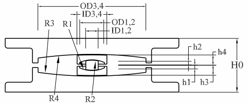
| element TFP $eleTag $iNode $jNode $R1 $R2 $R3 $R4 $D1 $D2 $D3 $D4 $d1 $d2 $d3 $d4 $mu1 $mu2 $mu3 $mu4 $h1 $h2 $h3 $h4 $H0 $colLoad <$K> |
| $eleTag | unique element object tag |
| $iNode $jNode | end nodes |
| $R1 | Radius of inner bottom sliding surface |
| $R2 | Radius of inner top sliding surface |
| $R3 | Radius of outer bottom sliding surface |
| $R4 | Radius of outer top sliding surface |
| $D1 | Diameter of inner bottom sliding surface |
| $D2 | Diameter of inner top sliding surface |
| $D3 | Diameter of outer bottom sliding surface |
| $D4 | Diameter of outer top sliding surface |
| $d1 | diameter of inner slider |
| $d2 | diameter of inner slider |
| $d3 | diameter of outer bottom slider |
| $d4 | diameter of outer top slider |
| $mu1 | friction coefficient of inner bottom sliding surface |
| $mu2 | friction coefficient of inner top sliding surface |
| $mu3 | friction coefficient of outer bottom sliding surface |
| $mu4 | friction coefficient of outer top sliding surface |
| $h1 | height from inner bottom sliding surface to center of bearing |
| $h2 | height from inner top sliding surface to center of bearing |
| $h3 | height from outer bottom sliding surface to center of bearing |
| $h4 | height from inner top sliding surface to center of bearing |
| $H0 | total height of bearing |
| $colLoad | initial axial load on bearing (only used for first time step then load come from model) |
| $K | optional, stiffness of spring in vertical dirn (dof 2 if ndm= 2, dof 3 if ndm = 3) (default=1.0e15) |
NOTE:
- If the element has zero length and optional orientation vectors are not specified, the local element axes coincide with the global axes. Otherwise the local z-axis is defined by the cross product between the x- and y-vectors specified on the command line.
- The valid queries to a triple friction pendulum bearing element when creating an ElementRecorder object are 'force,' 'localForce,' 'basicForce,' 'localDisplacement,' 'basicDisplacement', 'relativeDisp', 'plasticDisp', and 'material $matNum matArg1 matArg2 ...' Where $matNum is the number associated with the material whose data is to be output.
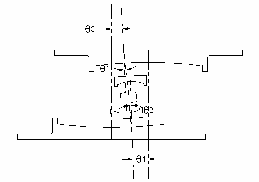
- relativeDisp returns relative displacements between the sliding components in the bearing. Relative displacements is the rotation (as shown in the figure above) multiplied by the respective radii. For each time step it returns 8 values; 4 for each horizontal direction.
- plasticDisp returns plastic displacements associated with relativeDisp
EXAMPLE:
element TFP 1 1 2 12.0 12.0 88.0 88.0 12.0 12.0 44.0 44.0 8.0 8.0 12.5 12.5 0.02 0.02 0.09 0.12 3.0 3.0 4.5 4.5 12.5 45.0;
REFERENCE:
Becker, TC, Mahin, SA. "Experimental and analytical study of the bi-directional behavior of the triple friction pendulum isolator," Earthquake Engineering and Structural Dynamics. (accepted for publication 03/11)read the paper
Code Developed by: Tracy Becker, University of California, Berkeley.


