Triple Friction Pendulum Element: Difference between revisions
No edit summary |
No edit summary |
||
| (63 intermediate revisions by 2 users not shown) | |||
| Line 1: | Line 1: | ||
{{CommandManualMenu}} | {{CommandManualMenu}} | ||
This command is used to construct a Triple Friction Pendulum Bearing element object. | This command is used to construct a Triple Friction Pendulum Bearing (TPB) (Figure 1) element object. The element is a 3-dimensional element with variable [http://opensees.berkeley.edu/wiki/index.php/FrictionModel_Command friction coefficient models] [1] [2]. The element accounts for the vertical-horizontal coupling and the bidirectional coupling in horizontal behavior. The friction coefficient model is a general model that accounts for the variation of friction coefficient on velocity and vertical force. Other simplified friction coefficient models such as vertical-force-independent friction coefficient, velocity-independent friction coefficient and constant friction coefficient can also be defined. The element can also be used for modeling single friction pendulum bearings or double friction pendulum bearings by simplifying the general backbone curve of the TPB. | ||
[[File:TPB_Nhan_Fig1.jpg|500px|center]] | |||
The horizontal normalized behavior of the element is an extension of the unidirectional behavior proposed by Fenz and Constantinou [3] and Morgan and Mahin [4]. The envelope normalized backbone curve for unidirectional behavior is in Figure 2 where effective radii are calculated from L_i=R_i- h_i, based on the bearing geometry in Figure 1. Displacements u_i^* and normalized forces f_i^* are evaluated according to [2], [3] or [4]. <span style="color:blue"> The Excel file for generating a backbone curve of a TPB can be downloaded here:</span>[[Media:TPB_Nhan_BackboneCurve.xls]] | |||
[[File:TPB_Nhan_Fig2.jpg|400px|center]] | |||
Overturning moment and torsion due to the eccentricity of internal forces are equally distributed to the 2 nodes of the element. | |||
In the vertical direction, the element is multi-linear elastic with different stiffnesses k_vc and k_vt in compression and tension, respectively. Even though a TPB has no resistance in tension, a small nonzero stiffness should be provided in tension for stability of the numerical procedure. The reasonable vertical stiffness in tension depends on the stiffness of the superstructure, but a value between 10 N/m to 100 N/m should work well in most cases. Very small ratio of k_vt/k_vc may cause the convergence difficulty when the superstructure is uplifted. | |||
{| | {| | ||
| style="background: | | style="background:lime; color:black; width:800px" | '''element TripleFrictionPendulum $eleTag $iNode $jNode $frnTag1 $frnTag2 $frnTag3 $vertMatTag $rotZMatTag $rotXMatTag $rotYMatTag $L1 $L2 $L3 $d1 $d2 $d3 $W $uy $kvt $minFv $tol''' | ||
|} | |} | ||
---- | ---- | ||
{| | {| | ||
| style="width: | | style="width:250px" | '''$eleTag''' || = unique element object tag | ||
|- | |||
| '''$iNode $jNode''' || = end nodes | |||
|- | |||
| '''$frnTag1, $frnTag2, $frnTag2''' || = tags associated with previously-defined [http://opensees.berkeley.edu/wiki/index.php/FrictionModel_Command FrictionModels] at the three sliding interfaces | |||
|- | |||
| '''$vertMatTag''' || = Pre-defined material tag for COMPRESSION behavior of the bearing | |||
|- | |||
| '''$rotZMatTag, $rotXMatTag, $rotYMatTag''' || = Pre-defined material tags for rotational behavior about 3-axis, 1-axis and 2-axis, respectively. | |||
|- | |||
| '''$L1, $L2, $L3''' || = effective radii. Li = R_i - h_i (see Figure 1) | |||
|- | |||
| '''$d1, $d2, $d3''' || = displacement limits of pendulums (Figure 1). Displacement limit of the bearing is 2$d1+$d2+$d3+$L1.$d3/$L3-$L1.$d2/$L2 | |||
|- | |||
| '''$W''' || = axial force used for the first trial of the first analysis step. | |||
|- | |- | ||
| '''$ | | '''$uy''' || = lateral displacement where sliding of the bearing starts. Recommended value = 0.25 to 1 mm. A smaller value may cause convergence problem. | ||
|- | |||
| '''$kvt''' || = Tension stiffness k_vt of the bearing. | |||
|- | |||
| '''$minFv (>=0)''' || = minimum vertical compression force in the bearing used for computing the horizontal tangent stiffness matrix from the normalized tangent stiffness matrix of the element. $minFv is substituted for the actual compressive force when it is less than $minFv, and prevents the element from using a negative stiffness matrix in the horizontal direction when uplift occurs. The vertical nodal force returned to nodes is always computed from $kvc (or $kvt) and vertical deformation, and thus is not affected by $minFv. | |||
|- | |||
| '''$tol''' || = relative tolerance for checking the convergence of the element. Recommended value = 1.e-10 to 1.e-3. | |||
|} | |} | ||
'''SPECIAL CASES:''' | |||
1. Vertical-horizontal uncoupled bearing: | |||
::Restrain vertical displacement of the 2 nodes and set $minFv = static vertical reaction of the bearing. | |||
2. Neglecting rotational stiffness: | |||
::Rotational stiffness of the bearing can be neglected by defining a very small value for the $rotXMatTag, $rotYMatTag and $rotZMatTag. However, using a too small number may cause a numerical convergence problem. | |||
'''NOTES:''' | |||
The current element requires 6 degree of freedoms at each node and defines the local coordinate system to be the same as the global coordinate system, where the vertical axis must be 3. | |||
Since the element accounts for the vertical-horizontal coupling behavior of TPBs, the time step size in analysis of vertically stiff structures should be small enough so that the high frequency components in responses can be captured. | |||
Rayleigh damping is automatically included when using Rayleigh command. | |||
The height of the bearing (for computing overturning moment from horizontal force) is computed from the vertical distance between the two end nodes. | |||
---- | ---- | ||
EXAMPLE: | '''EXAMPLE:''' | ||
frictionModel VelNormalFrcDep 1 [expr 0.012/pow($W,0.8-1.0)] 0.8 [expr 0.018/pow($W,0.7-1.0)] 0.7 25.0 0.0 0.0 3.0 | |||
frictionModel VelNormalFrcDep 2 [expr 0.052/pow($W,0.8-1.0)] 0.8 [expr 0.075/pow($W,0.7-1.0)] 0.7 25.0 0.0 0.0 3.0 | |||
frictionModel VelNormalFrcDep 3 [expr 0.12/pow($W,0.8-1.0)] 0.8 [expr 0.16/pow($W,0.7-1.0)] 0.7 25.0 0.0 0.0 3.0 | |||
uniaxialMaterial Elastic 1 1.e6 | |||
uniaxialMaterial Elastic 2 100.; | |||
2 | uniaxialMaterial Elastic 3 100.; | ||
uniaxialMaterial Elastic 4 10.; | |||
element TripleFrictionPendulum 1 1 2 1 2 3 1 4 2 3 0.36 1.25 1.25 0.1 0.2 0.2 1000.0 0.0005 1.0 0.1 1.E-5; | |||
---- | ---- | ||
'''REFERENCES:''' | |||
[1] Dao ND, Ryan KL, Sato E, Sasaki T. Predicting the displacement of triple pendulum™ bearings in a full-scale shaking experiment using a three-dimensional element. Earthquake Engineering and Structural Dynamics, 2013. | |||
[2] Dao ND. Seismic Response of a Full-scale 5-story Steel Frame Building Isolated by Triple Pendulum Bearings under 3D Excitations. Dissertation, University of Nevada – Reno, 2012. | |||
[3] Fenz DM, Constantinou MC. Spherical sliding isolation bearings with adaptive behavior: Theory. Earthquake Engineering and Structural Dynamics 2008; 37(2):163-183. | |||
[4] Morgan TA, Mahin SA. The use of innovative base isolation systems to achieve complex seismic performance objectives. PEER-2011/06 2011. | |||
---- | ---- | ||
EXAMPLE 1: Unidirectional static pushover of a TPB element with constant friction coefficients. | Code Developed by: <span style="color:blue"> Nhan D. Dao, University of Nevada - Reno. E-mail: nhan.unr@gmail.com </span>. | ||
---- | |||
{| | |||
| style="background:yellow; color:black" | '''APPLICATION EXAMPLES''' | |||
|} | |||
Download these 3 ground motion files and change the extension ".tcl" to ".ATH" for EXAMPLES 2 to 7: [[Media:TCU065-E.tcl]], [[Media:TCU065-N.tcl]], [[Media:TCU065-V.tcl]] | |||
{| | |||
| style="background:yellow; color:black" | '''EXAMPLE 1:''' | |||
|} | |||
Unidirectional static pushover of a TPB element with constant friction coefficients. | |||
Tcl code: [[Media:CheckingTripleFrictionPendulum_StaticCyclicPushover.tcl]] | Tcl code: [[Media:CheckingTripleFrictionPendulum_StaticCyclicPushover.tcl]] | ||
| Line 51: | Line 147: | ||
EXAMPLE 2: Unidirectional dynamic seismic analysis of a single mass supported by a TPB element with constant friction coefficients. | {| | ||
| style="background:yellow; color:black" | '''EXAMPLE 2:''' | |||
|} | |||
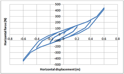
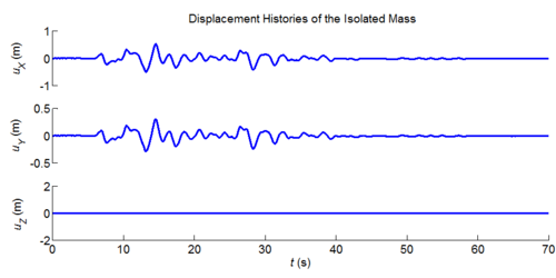
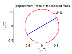
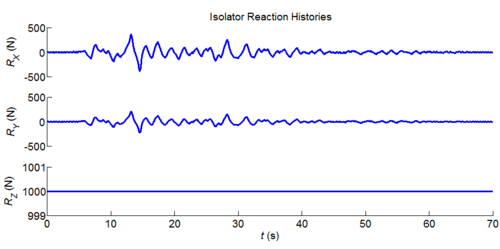
Unidirectional dynamic seismic analysis of a single mass supported by a TPB element with constant friction coefficients. | |||
Tcl code: [[Media:CheckingTripleFrictionPendulum_1DDynamics_ConstFriction.tcl]] | Tcl code: [[Media:CheckingTripleFrictionPendulum_1DDynamics_ConstFriction.tcl]] | ||
| Line 57: | Line 157: | ||
Results: | Results: | ||
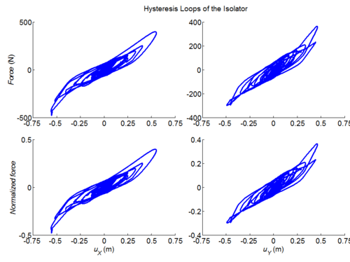
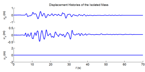
[[File:TPB_Nhan_Ex2_1Disp.png| | [[File:TPB_Nhan_Ex2_1Disp.png|500px]] | ||
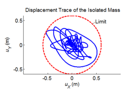
[[File:TPB_Nhan_Ex2_2DispTrace.png| | [[File:TPB_Nhan_Ex2_2DispTrace.png|250px]] | ||
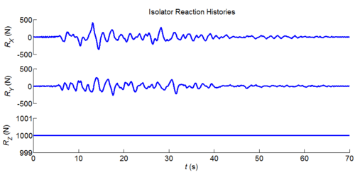
[[File:TPB_Nhan_Ex2_3Reaction.png| | [[File:TPB_Nhan_Ex2_3Reaction.png|500px]] | ||
[[File:TPB_Nhan_Ex2_4Loop.png| | [[File:TPB_Nhan_Ex2_4Loop.png|500px]] | ||
EXAMPLE 3: Unidirectional dynamic seismic analysis of a single mass supported by a TPB element with variable friction coefficients. | {| | ||
| style="background:yellow; color:black" | '''EXAMPLE 3:''' | |||
|} | |||
Unidirectional dynamic seismic analysis of a single mass supported by a TPB element with variable friction coefficients. | |||
Tcl code: [[Media:CheckingTripleFrictionPendulum_1DDynamics_VariableFriction.tcl]] | Tcl code: [[Media:CheckingTripleFrictionPendulum_1DDynamics_VariableFriction.tcl]] | ||
| Line 74: | Line 178: | ||
Results: | Results: | ||
[[File:TPB_Nhan_Ex3_1Disp.png| | [[File:TPB_Nhan_Ex3_1Disp.png|500px]] | ||
[[File:TPB_Nhan_Ex3_2DispTrace.png| | [[File:TPB_Nhan_Ex3_2DispTrace.png|250px]] | ||
[[File:TPB_Nhan_Ex3_3Reaction.png| | [[File:TPB_Nhan_Ex3_3Reaction.png|500px]] | ||
[[File:TPB_Nhan_Ex3_4Loop.png| | [[File:TPB_Nhan_Ex3_4Loop.png|500px]] | ||
EXAMPLE 4: | {| | ||
| style="background:yellow; color:black" | '''EXAMPLE 4:''' | |||
|} | |||
Two-dimensional dynamic seismic analysis of a single mass supported by a TPB element with constant friction coefficients. | |||
Tcl code: [[Media:CheckingTripleFrictionPendulum_2DDynamic_ConstFriction.tcl]] | Tcl code: [[Media:CheckingTripleFrictionPendulum_2DDynamic_ConstFriction.tcl]] | ||
| Line 90: | Line 198: | ||
Results: | Results: | ||
[[File:TPB_Nhan_Ex4_1Disp.png| | [[File:TPB_Nhan_Ex4_1Disp.png|500px]] | ||
[[File:TPB_Nhan_Ex4_2DispTrace.png| | [[File:TPB_Nhan_Ex4_2DispTrace.png|250px]] | ||
[[File:TPB_Nhan_Ex4_3aReaction.png| | [[File:TPB_Nhan_Ex4_3aReaction.png|500px]] | ||
[[File:TPB_Nhan_Ex4_4Loop.png| | [[File:TPB_Nhan_Ex4_4Loop.png|500px]] | ||
EXAMPLE 5: | {| | ||
| style="background:yellow; color:black" | '''EXAMPLE 5:''' | |||
|} | |||
Two-dimensional dynamic seismic analysis of a single mass supported by a TPB element with variable friction coefficients. | |||
Tcl code: [[Media:CheckingTripleFrictionPendulum_2DDynamic_VariableFriction.tcl]] | Tcl code: [[Media:CheckingTripleFrictionPendulum_2DDynamic_VariableFriction.tcl]] | ||
| Line 107: | Line 219: | ||
Results: | Results: | ||
[[File:TPB_Nhan_Ex5_1Disp.png| | [[File:TPB_Nhan_Ex5_1Disp.png|500px]] | ||
[[File:TPB_Nhan_Ex5_2Trace.png|250px]] | |||
[[File: | [[File:TPB_Nhan_Ex5_3Reaction.png|500px]] | ||
[[File: | [[File:TPB_Nhan_Ex5_4aLoop.png|500px]] | ||
{| | |||
| style="background:yellow; color:black" | '''EXAMPLE 6:''' | |||
|} | |||
Three-dimensional dynamic seismic analysis of a single mass supported by a TPB element with constant friction coefficients. | |||
Tcl code: [[Media:CheckingTripleFrictionPendulum_3DDynamic_ConstFriction.tcl]] | Tcl code: [[Media:CheckingTripleFrictionPendulum_3DDynamic_ConstFriction.tcl]] | ||
| Line 124: | Line 240: | ||
Results: | Results: | ||
[[File:TPB_Nhan_Ex6_1Disp.png| | [[File:TPB_Nhan_Ex6_1Disp.png|500px]] | ||
[[File:TPB_Nhan_Ex6_2DispTrace.png| | [[File:TPB_Nhan_Ex6_2DispTrace.png|250px]] | ||
[[File:TPB_Nhan_Ex6_3Reaction.png| | [[File:TPB_Nhan_Ex6_3Reaction.png|500px]] | ||
[[File:TPB_Nhan_Ex6_4Loop.png| | [[File:TPB_Nhan_Ex6_4Loop.png|500px]] | ||
EXAMPLE 7: | {| | ||
| style="background:yellow; color:black" | '''EXAMPLE 7:''' | |||
|} | |||
Three-dimensional dynamic seismic analysis of a single mass supported by a TPB element with variable friction coefficients. | |||
Tcl code: [[Media:CheckingTripleFrictionPendulum_3DDynamic_VariableFriction.tcl]] | Tcl code: [[Media:CheckingTripleFrictionPendulum_3DDynamic_VariableFriction.tcl]] | ||
| Line 141: | Line 261: | ||
Results: | Results: | ||
[[File:TPB_Nhan_Ex7_1Disp.png| | [[File:TPB_Nhan_Ex7_1Disp.png|500px]] | ||
[[File:TPB_Nhan_Ex7_2DispTrace.png| | [[File:TPB_Nhan_Ex7_2DispTrace.png|250px]] | ||
[[File:TPB_Nhan_Ex7_3Reaction.png| | [[File:TPB_Nhan_Ex7_3Reaction.png|500px]] | ||
[[File:TPB_Nhan_Ex7_4Loop.png| | [[File:TPB_Nhan_Ex7_4Loop.png|500px]] | ||
Latest revision as of 06:54, 16 August 2017
- Command_Manual
- Tcl Commands
- Modeling_Commands
- model
- uniaxialMaterial
- ndMaterial
- frictionModel
- section
- geometricTransf
- element
- node
- sp commands
- mp commands
- timeSeries
- pattern
- mass
- block commands
- region
- rayleigh
- Analysis Commands
- Output Commands
- Misc Commands
- DataBase Commands
This command is used to construct a Triple Friction Pendulum Bearing (TPB) (Figure 1) element object. The element is a 3-dimensional element with variable friction coefficient models [1] [2]. The element accounts for the vertical-horizontal coupling and the bidirectional coupling in horizontal behavior. The friction coefficient model is a general model that accounts for the variation of friction coefficient on velocity and vertical force. Other simplified friction coefficient models such as vertical-force-independent friction coefficient, velocity-independent friction coefficient and constant friction coefficient can also be defined. The element can also be used for modeling single friction pendulum bearings or double friction pendulum bearings by simplifying the general backbone curve of the TPB.
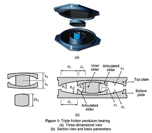
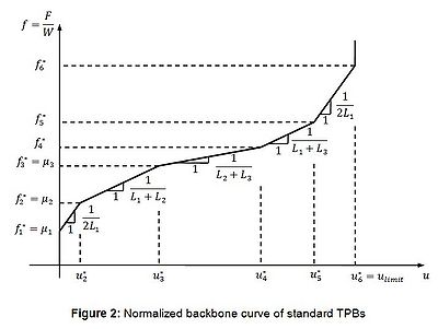
The horizontal normalized behavior of the element is an extension of the unidirectional behavior proposed by Fenz and Constantinou [3] and Morgan and Mahin [4]. The envelope normalized backbone curve for unidirectional behavior is in Figure 2 where effective radii are calculated from L_i=R_i- h_i, based on the bearing geometry in Figure 1. Displacements u_i^* and normalized forces f_i^* are evaluated according to [2], [3] or [4]. The Excel file for generating a backbone curve of a TPB can be downloaded here:Media:TPB_Nhan_BackboneCurve.xls
Overturning moment and torsion due to the eccentricity of internal forces are equally distributed to the 2 nodes of the element.
In the vertical direction, the element is multi-linear elastic with different stiffnesses k_vc and k_vt in compression and tension, respectively. Even though a TPB has no resistance in tension, a small nonzero stiffness should be provided in tension for stability of the numerical procedure. The reasonable vertical stiffness in tension depends on the stiffness of the superstructure, but a value between 10 N/m to 100 N/m should work well in most cases. Very small ratio of k_vt/k_vc may cause the convergence difficulty when the superstructure is uplifted.
| element TripleFrictionPendulum $eleTag $iNode $jNode $frnTag1 $frnTag2 $frnTag3 $vertMatTag $rotZMatTag $rotXMatTag $rotYMatTag $L1 $L2 $L3 $d1 $d2 $d3 $W $uy $kvt $minFv $tol |
| $eleTag | = unique element object tag |
| $iNode $jNode | = end nodes |
| $frnTag1, $frnTag2, $frnTag2 | = tags associated with previously-defined FrictionModels at the three sliding interfaces |
| $vertMatTag | = Pre-defined material tag for COMPRESSION behavior of the bearing |
| $rotZMatTag, $rotXMatTag, $rotYMatTag | = Pre-defined material tags for rotational behavior about 3-axis, 1-axis and 2-axis, respectively. |
| $L1, $L2, $L3 | = effective radii. Li = R_i - h_i (see Figure 1) |
| $d1, $d2, $d3 | = displacement limits of pendulums (Figure 1). Displacement limit of the bearing is 2$d1+$d2+$d3+$L1.$d3/$L3-$L1.$d2/$L2 |
| $W | = axial force used for the first trial of the first analysis step. |
| $uy | = lateral displacement where sliding of the bearing starts. Recommended value = 0.25 to 1 mm. A smaller value may cause convergence problem. |
| $kvt | = Tension stiffness k_vt of the bearing. |
| $minFv (>=0) | = minimum vertical compression force in the bearing used for computing the horizontal tangent stiffness matrix from the normalized tangent stiffness matrix of the element. $minFv is substituted for the actual compressive force when it is less than $minFv, and prevents the element from using a negative stiffness matrix in the horizontal direction when uplift occurs. The vertical nodal force returned to nodes is always computed from $kvc (or $kvt) and vertical deformation, and thus is not affected by $minFv. |
| $tol | = relative tolerance for checking the convergence of the element. Recommended value = 1.e-10 to 1.e-3. |
SPECIAL CASES:
1. Vertical-horizontal uncoupled bearing:
- Restrain vertical displacement of the 2 nodes and set $minFv = static vertical reaction of the bearing.
2. Neglecting rotational stiffness:
- Rotational stiffness of the bearing can be neglected by defining a very small value for the $rotXMatTag, $rotYMatTag and $rotZMatTag. However, using a too small number may cause a numerical convergence problem.
NOTES:
The current element requires 6 degree of freedoms at each node and defines the local coordinate system to be the same as the global coordinate system, where the vertical axis must be 3.
Since the element accounts for the vertical-horizontal coupling behavior of TPBs, the time step size in analysis of vertically stiff structures should be small enough so that the high frequency components in responses can be captured.
Rayleigh damping is automatically included when using Rayleigh command.
The height of the bearing (for computing overturning moment from horizontal force) is computed from the vertical distance between the two end nodes.
EXAMPLE:
frictionModel VelNormalFrcDep 1 [expr 0.012/pow($W,0.8-1.0)] 0.8 [expr 0.018/pow($W,0.7-1.0)] 0.7 25.0 0.0 0.0 3.0
frictionModel VelNormalFrcDep 2 [expr 0.052/pow($W,0.8-1.0)] 0.8 [expr 0.075/pow($W,0.7-1.0)] 0.7 25.0 0.0 0.0 3.0
frictionModel VelNormalFrcDep 3 [expr 0.12/pow($W,0.8-1.0)] 0.8 [expr 0.16/pow($W,0.7-1.0)] 0.7 25.0 0.0 0.0 3.0
uniaxialMaterial Elastic 1 1.e6
uniaxialMaterial Elastic 2 100.;
uniaxialMaterial Elastic 3 100.;
uniaxialMaterial Elastic 4 10.;
element TripleFrictionPendulum 1 1 2 1 2 3 1 4 2 3 0.36 1.25 1.25 0.1 0.2 0.2 1000.0 0.0005 1.0 0.1 1.E-5;
REFERENCES:
[1] Dao ND, Ryan KL, Sato E, Sasaki T. Predicting the displacement of triple pendulum™ bearings in a full-scale shaking experiment using a three-dimensional element. Earthquake Engineering and Structural Dynamics, 2013.
[2] Dao ND. Seismic Response of a Full-scale 5-story Steel Frame Building Isolated by Triple Pendulum Bearings under 3D Excitations. Dissertation, University of Nevada – Reno, 2012.
[3] Fenz DM, Constantinou MC. Spherical sliding isolation bearings with adaptive behavior: Theory. Earthquake Engineering and Structural Dynamics 2008; 37(2):163-183.
[4] Morgan TA, Mahin SA. The use of innovative base isolation systems to achieve complex seismic performance objectives. PEER-2011/06 2011.
Code Developed by: Nhan D. Dao, University of Nevada - Reno. E-mail: nhan.unr@gmail.com .
| APPLICATION EXAMPLES |
Download these 3 ground motion files and change the extension ".tcl" to ".ATH" for EXAMPLES 2 to 7: Media:TCU065-E.tcl, Media:TCU065-N.tcl, Media:TCU065-V.tcl
| EXAMPLE 1: |
Unidirectional static pushover of a TPB element with constant friction coefficients.
Tcl code: Media:CheckingTripleFrictionPendulum_StaticCyclicPushover.tcl
Results:
| EXAMPLE 2: |
Unidirectional dynamic seismic analysis of a single mass supported by a TPB element with constant friction coefficients.
Tcl code: Media:CheckingTripleFrictionPendulum_1DDynamics_ConstFriction.tcl
Results:
| EXAMPLE 3: |
Unidirectional dynamic seismic analysis of a single mass supported by a TPB element with variable friction coefficients.
Tcl code: Media:CheckingTripleFrictionPendulum_1DDynamics_VariableFriction.tcl
Results:
| EXAMPLE 4: |
Two-dimensional dynamic seismic analysis of a single mass supported by a TPB element with constant friction coefficients.
Tcl code: Media:CheckingTripleFrictionPendulum_2DDynamic_ConstFriction.tcl
Results:
| EXAMPLE 5: |
Two-dimensional dynamic seismic analysis of a single mass supported by a TPB element with variable friction coefficients.
Tcl code: Media:CheckingTripleFrictionPendulum_2DDynamic_VariableFriction.tcl
Results:
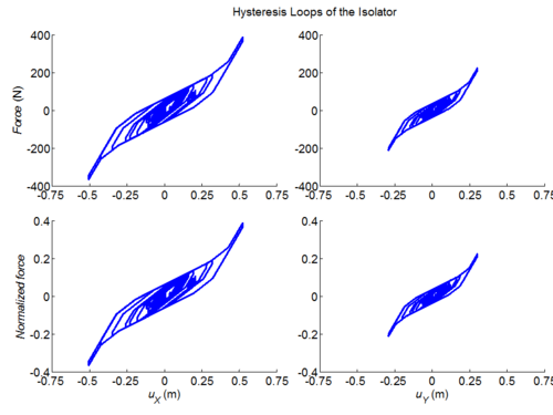
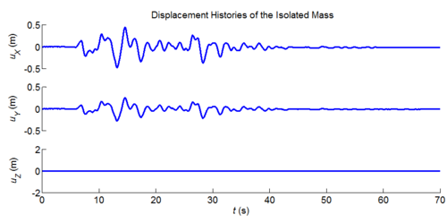
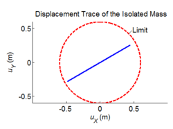
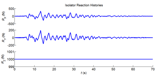
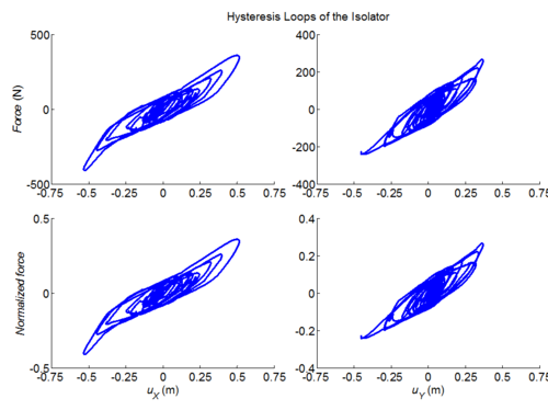
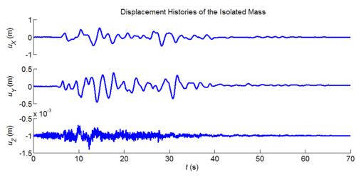
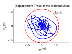
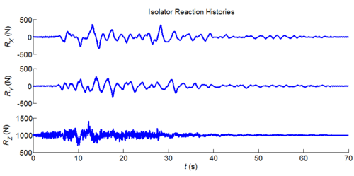
| EXAMPLE 6: |
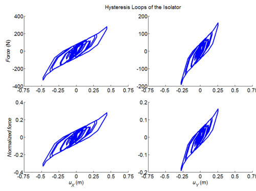
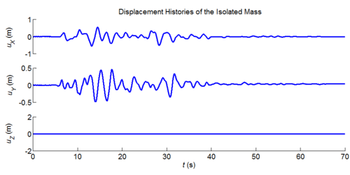
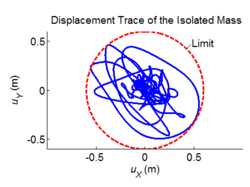
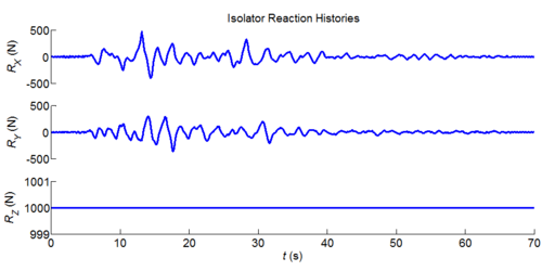
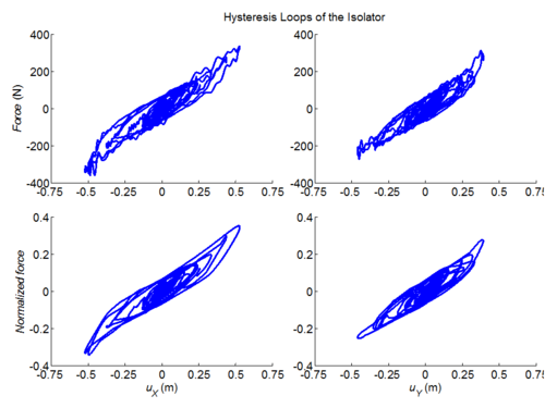
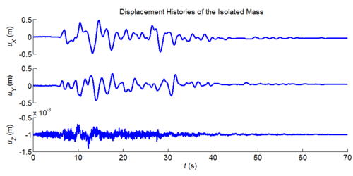
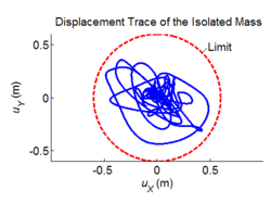
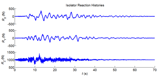
Three-dimensional dynamic seismic analysis of a single mass supported by a TPB element with constant friction coefficients.
Tcl code: Media:CheckingTripleFrictionPendulum_3DDynamic_ConstFriction.tcl
Results:
| EXAMPLE 7: |
Three-dimensional dynamic seismic analysis of a single mass supported by a TPB element with variable friction coefficients.
Tcl code: Media:CheckingTripleFrictionPendulum_3DDynamic_VariableFriction.tcl
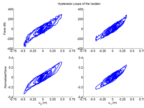
Results:
